Since I wrote “Secrets of SMD” it is now more an a year. At that time a soldering iron was my favourite soldering tool. In between I tried table grill ovens and a pizza skillet (=electric pizza pan) as reflow device. Success rate varied a lot with molten dark parts (=high absorption) & unsoldered silver ones (=low absorption), no possibility to interfere in the running process & generally quite dark PCBs (overheated boards).
Today I mainly use SMD soldered on a clothing iron, use a hot air gun for the back of double sided or very simple single sided PCBs & the soldering iron mainly for small corrections or soldering connectors.
This is an overview of my recent process of DIY production of PCBs. I hope it is not too sketchy, cause I do this write-up in the pauses of board making with exactly this process – I am quite new to it – it´s fresh!
See it is a starting point for your own fast prototype-production or just a way to share some ideas.
Toolz of our Business
First we have the hot air gun, a gas burner with catalyst, you can get it for about 20 EUR. Its useful for any re-work (de-soldering & repair) of multi-pin devices. Be careful not to overheat parts.
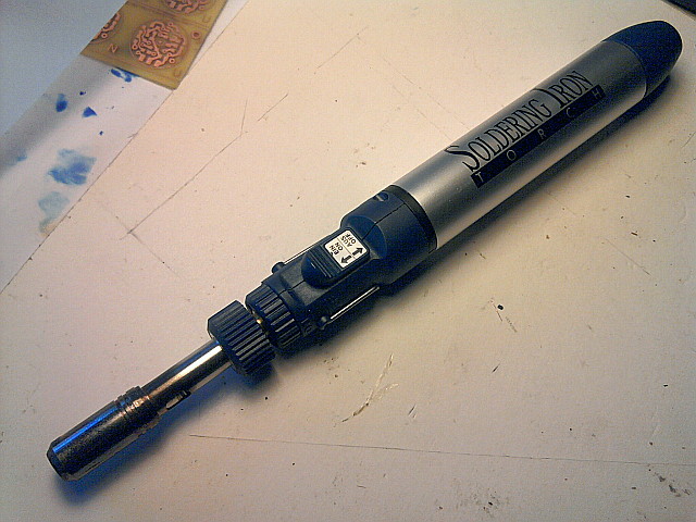
The Hot Air Gun
Hot Air Gun, Catalyst glowing
Next comes a hot plate, which can also be an electric pizza pan I used before. A clothing iron has the advantage that you can also use it for the toner PCB method or heating etching solution, it´s flat & heats up very fast. Fix it to a table with a clamp in a horizontal position:
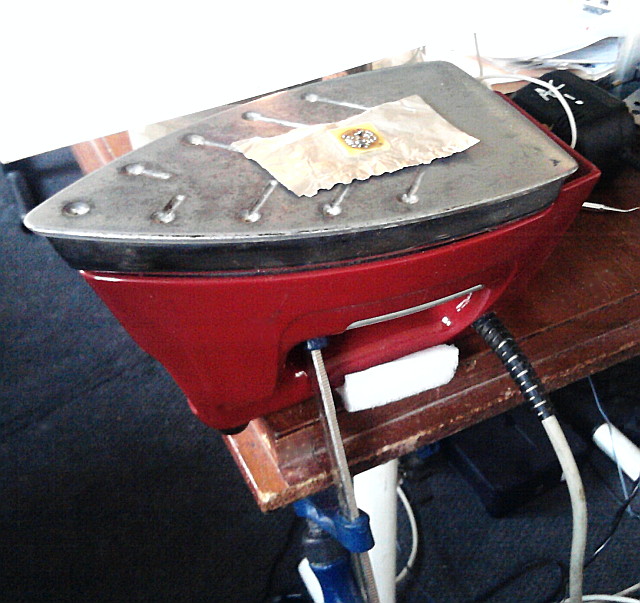
Clothing Iron fixed to Table
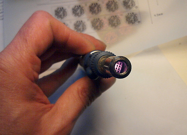
Next we need hypodermic needles for the application of solder paste. I prefer the black 22G size, sometimes 20G. (Updated with this nice table)
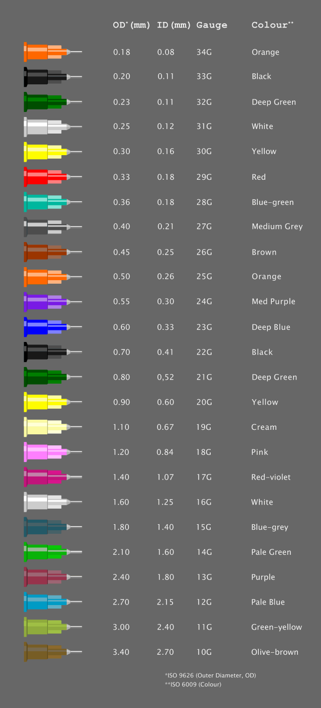
Table with Needle Colour Codes
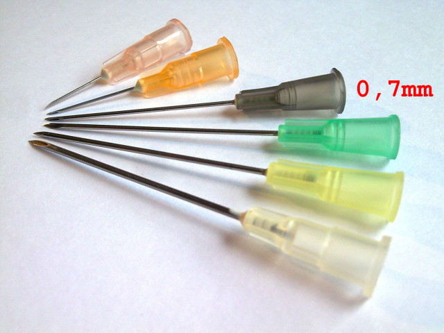
Hypodermic Needles / CC 3.0 Attribution: Zephyris
For breaking the needle I scratch the surface with an electronic cutter, rotating the needle several times:
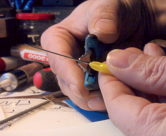
Scratching the Needle Surface
Then it is like breaking glass tubes, pull & bend at the same time:
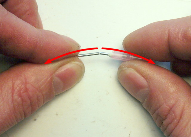
Breaking a Needle
After deburring on sandpaper or a sharpening stone we get a nice blunt shortened needle – as syringe I use a 1ml size with a silicone stopper, types with plastic stopper do not have a smooth action (the needed ones are sold as “latex-free” insulin syringes):
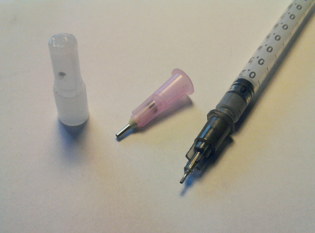
Cut & deburred
Against drying out of the solder paste I store the filled syringes in an old marmalade container with a tight lid, some drops of IPA (Iso Propyl Alcohol) or pure ethyl alcohol are added, the cap I shortened by melting with hot air:
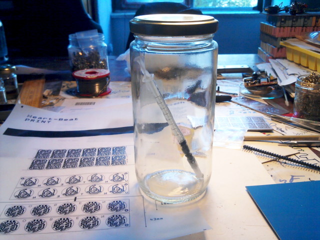
Syringe Container with Alcohol Vapor against drying out
Materials
Flux is used to cover the PCB before soldering. I produce it in two forms, as a liquid and with a honey like consistency by dissolving violin rosin in IPA. 1:10 volume ratio for the liquid, about 2:1 for the paste, which means dissolving as much as possible in warm IPA. Crystallisation forming the paste occurs on cooling. It´s more like making jam.
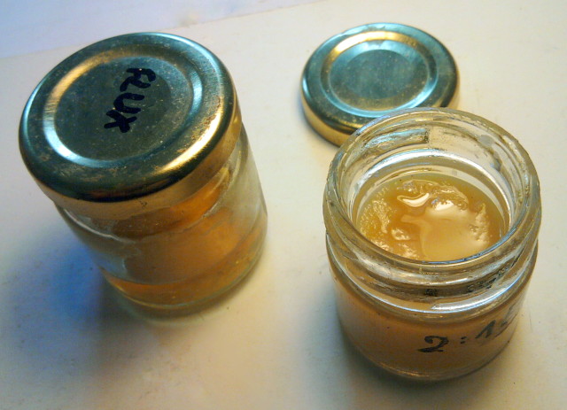
DIY Fluxes from Violin Rosin
Here is the cheap Chinese solder paste I use. I guess it is meant for silk-screening. Adding IPA drop-wise may be necessary to get the heavy sticky liquid state we need for our purposes.
If you know some really good lead-free solder paste I may switch in the future. But most probably the 20..30°C higher process temperature needed will force us to use some different techniques.
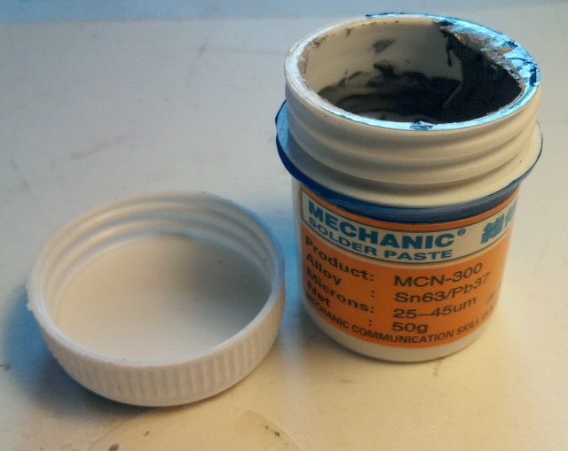
Solder Paste
Experiment!
I almost forgot the most important point: Try out things to get a feeling for the process & check your materials.
In this example you can see how I marked two cleaned areas, one with the excellent “Mechanic” solder paste to the far left, the other area with a more “professional” paste which needs a totally different process & does not work here.
In the right area I tried my first needle looking for dot sizes & how the paste performs on a oxidized/uncleaned copper surface:
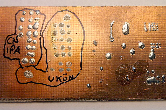
Experiments with Solder & Fluxes
Solder Paste Application
A little drop of solder paste is squeezed from the blunt needle and applied as a small dot on the PCB. Pointed tweezers are helpful in placing SMD parts.
(BTW: I don´t like comments like “your fingernails need cutting” – no, they are useful for work!):
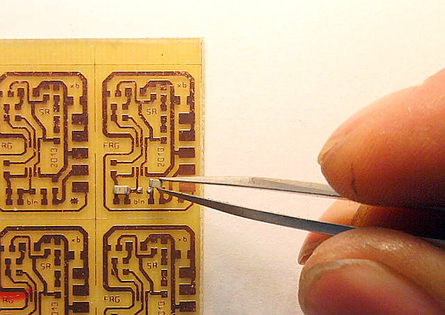
SMD Placement
On complex boards, think strategically. Try to put fine-pitched parts (small distance between neighbouring legs) first, you may have to correct their placement a lot or even to wipe off all their paste. This is hard to do in a stuffed corner.
All two-terminal parts are easy – I just apply paste for the next two to five parts & drop them in position. I don’t know if that is necessary or even harmful, but I press them down a bit – I don’t want to loose parts when handling the board later.
Bulky parts come last. They are always in the way & it needs more concentration to not touch them erroneously.
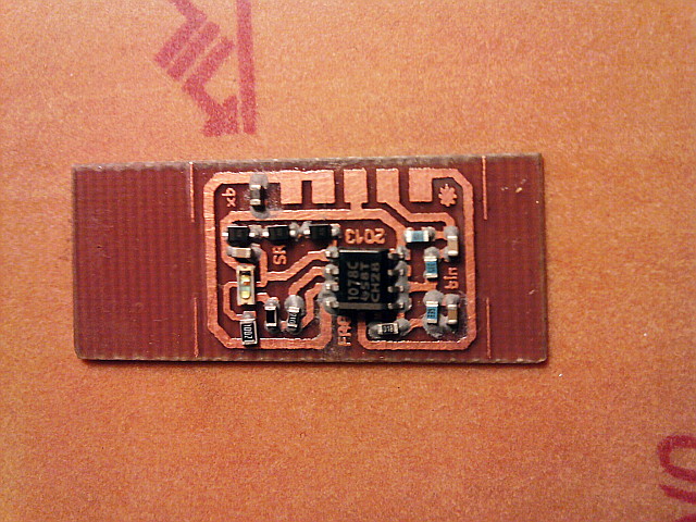
Solder Paste applied with 0603 SMD parts
Reflow:
First we need to bake the paste for some minutes. I use 10mins on “Silk” then heat up 20secs to “Cotton” – here the solder paste smokes a bit, the flux does its cleaning & flowing. Finally boost up to “Linen”.
Then reflow (= melting) occurs, stay there 15secs, eventually pressing down the PCB with some pointed instrument like a small screwdriver for to reach peak temperature. Then slide off to an unheated non-metallic surface to cool down slowly. Listen to the clicks of the iron´s temperature regulator, they give acoustic feedback of the temperature you reached. Use no steam 🙂
At the reflow point you may notice several wonderful things: surface tension of the molten solder pulls together smeared solder paste & parts start sliding a bit to “click” in position if unprecisely placed. This sliding effect depends on the board design – datasheets provide you with optimized PCB patterns for this to happen if you run into problems with your design program´s generic patterns. Don’t expect everything to work the very first time.
Some caveats: An over-rapid heat transfer can cause solder splattering and the production of solder balls, bridging and other defects. If the heat transfer is too slow, the flux concentration may remain high and result in cold solder joints, voids and incomplete reflow.
When I have to deal with through hole connections I put aluminium foil under the PCB.
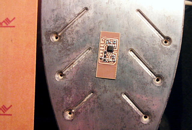
Reflow on the Hot Iron
Success!
Finally check for shorts between adjacent IC legs. SMD-probes are useful. In any case do a visual inspection with a magnifying glass, I use a 6x & have the feeling 10x is best for our work.
Because our flux is pure rosin, it is “no clean” and can stay on the the final PCB. Cleaning with IPA and a toothbrush is also possible.
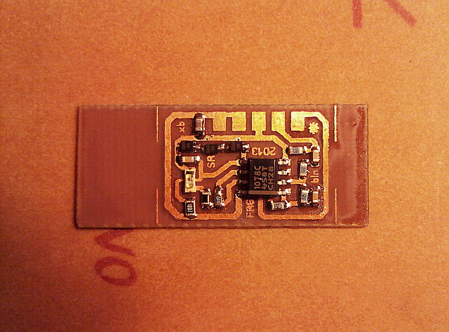
Finished soldering

Thanks! Just venturing into SMD work. Altho’ well experienced in electronics, I need to drag my company, screaming and kicking, into the 21st century.
Unfortunately, I’m also 59 years old, so my eyesight aint what it was….But I soldered a couple of TI ADS7828 a/d converters, with 0,5mm pitch yesterday – doddle.
However, SMD’s have their disadvantages….My last Facebook post…
FRIDAY GEEK ALERT!
Didn’t realise how expensive my sneezing was until yesterday….
I had three FET’s on my table. All surface mount devices (SMD’s). €1 each.
Sneezed, and they vanished! About this size, but black. Mouse-shit is bigger!
http://tinyurl.com/pr58s72
Definite case of:
http://sd.keepcalm-o-matic.co.uk/i/get-on-your-knees-and-smd.png
(found 2…)
Comment by ANdy — 16 January 2015 @ 17:59